Kiston Precision Machinery


Series:
S2/S4 Series Straight Side Eccentric Gear Press
Series
Phone
Fax


Detailed Introduction
Description
S2/S4 Series|Straight Side Eccentric Gear Press
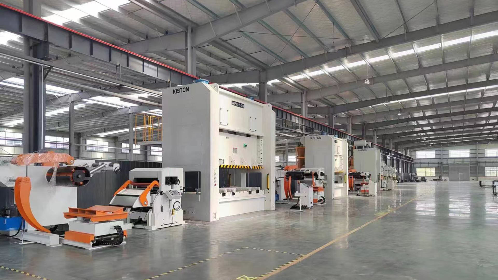
As an excellent equipment for processing high-tensile steel panels, the SE series with tough rigidity is mainly applied with large dies in automotive industry. The model adopts design of eccentric gear drive component and 8-point guided slide for high precision. The design of energy and electricity conservation allows saving more than 20% of energy and the large overload capacity extends the lifetime of use.
Model : S2-400~1200 / S4-400~2400
Features
Designed with tie-rod structure on the frame for minimal deflection enhance machine durability with accurate parts.
Design makes it easy to integrate automation.
Excellent performance in automatic feed,progressive die or single stroke applications.
Eccentric gear drive, excellent for deep drawing and a variety of other stamping applications.
Plunger guided to reduces lateral force during slide movement for better accuracy.
Column mounted operating panel, intuitive read outs and easy to use, convenient, controls.
| Item | Unit | S2‑400 | S2‑500 | S2‑600 | S2‑800 | S2‑1000 | S2‑1200 | S4‑500 | S4‑600 | S4‑800 | S4‑1000 | S4‑1200 | S4‑1600 | S4‑2000 | S4‑2400 |
| Type | ‑ | S | S | S | S | S | S | S | S | S | S | S | S | S | S |
| Capacity | kN | 4000 | 5000 | 6000 | 8000 | 10000 | 12000 | 5000 | 6000 | 8000 | 10000 | 12000 | 16000 | 20000 | 24000 |
| Stroke Length | mm | 500 | 500 | 500 | 600 | 600 | 800 | 500 | 500 | 600 | 600 | 800 | 800 | 900 | 1000 |
| Strokes per Minute | SPM | 15‑26 | 12‑24 | 12‑22 | 10‑18 | 10‑18 | 10‑18 | 12‑24 | 12‑22 | 10‑20 | 10‑20 | 10‑20 | 10‑20 | 10‑20 | 10‑20 |
| Tonnage Rating Point | mm | 13 | 13 | 13 | 13 | 13 | 13 | 13 | 13 | 13 | 13 | 13 | 13 | 13 | 13 |
| Die Height | mm | 700 | 800 | 800 | 1000 | 1000 | 1100 | 800 | 800 | 1000 | 1000 | 1100 | 1200 | 1300 | 1400 |
| Slide Adjustment | mm | 300 | 400 | 400 | 400 | 400 | 500 | 400 | 400 | 400 | 400 | 500 | 500 | 600 | 600 |
| Slide Area (LR×FB)‑Option1 | mm | 2500×1400 | 2500×1450 | 2500×1550 | 2800×1700 | 3100×1700 | 3400×1700 | 2500×2000 | 2500×2000 | 2800×2200 | 3100×2200 | 3400×2200 | 3400×2200 | 4000×2200 | 4000×2200 |
| Slide Area (LR×FB)‑Option2 | mm | 2800×1400 | 2800×1450 | 2800×1550 | 3100×1700 | 3400×1700 | 3700×1700 | 2800×2000 | 2800×2000 | 3100×2200 | 3400×2200 | 3700×2200 | 3700×2200 | 4300×2200 | 4300×2200 |
| Slide Area (LR×FB)‑Option3 | mm | 3100×1400 | 3100×1450 | 3100×1550 | 3400×1700 | 3700×1700 | 4000×1700 | 3100×2000 | 3100×2000 | 3400×2200 | 3700×2200 | 4000×2200 | 4000×2200 | 4600×2200 | 4600×2200 |
| Slide Area (LR×FB)‑Option4 | mm | 3400×1400 | 3400×1450 | 3400×1550 | 3700×1700 | 4000×1700 | 4300×1700 | 3400×2000 | 3400×2000 | 3700×2200 | 4000×2200 | 4300×2200 | 4300×2200 | 4900×2200 | 4900×2200 |
| Bolster Area (LR×FB)‑Option1 | mm | 2500×1400 | 2500×1450 | 2500×1550 | 2800×1700 | 3100×1700 | 3400×1700 | 2500×2000 | 2500×2000 | 2800×2200 | 3100×2200 | 3400×2200 | 3400×2200 | 4000×2200 | 4000×2200 |
| Bolster Area (LR×FB)‑Option2 | mm | 2800×1400 | 2800×1450 | 2800×1550 | 3100×1700 | 3400×1700 | 3700×1700 | 2800×2000 | 2800×2000 | 3100×2200 | 3400×2200 | 3700×2200 | 3700×2200 | 4300×2200 | 4300×2200 |
| Bolster Area (LR×FB)‑Option3 | mm | 3100×1400 | 3100×1450 | 3100×1550 | 3400×1700 | 3700×1700 | 4000×1700 | 3100×2000 | 3100×2000 | 3400×2200 | 3700×2200 | 4000×2200 | 4000×2200 | 4600×2200 | 4600×2200 |
| Bolster Area (LR×FB)‑Option4 | mm | 3400×1400 | 3400×1450 | 3400×1550 | 3700×1700 | 4000×1700 | 4300×1700 | 3400×2000 | 3400×2000 | 3700×2200 | 4000×2200 | 4300×2200 | 4300×2200 | 4900×2200 | 4900×2200 |
| Bolster Thickness | mm | 180 | 180 | 250 | 250 | 250 | 300 | 180 | 250 | 250 | 250 | 300 | 300 | 300 | 300 |
| Max. Upper Die Weight | Ton | 5 | 6 | 6 | 7 | 7 | 8 | 8 | 9 | 10 | 10 | 11 | 13 | 15 | 20 |
| Required Air Pressure | MPa | 0.6 | 0.6 | 0.6 | 0.6 | 0.6 | 0.6 | 0.6 | 0.6 | 0.6 | 0.6 | 0.6 | 0.6 | 0.6 | 0.6 |
| Fixed Bolster Height | mm | 850 | 850 | 850 | 850 | 850 | 850 | 850 | 850 | 850 | 850 | 850 | 850 | 850 | 850 |
| Rolling Bolster Height | mm | 660 | 660 | 660 | 660 | 740 | 740 | 660 | 660 | 660 | 740 | 740 | 740 | 740 | 740 |
Specifications
Detailed Configuration
Keywords:
High-precision powerful steel frame punching machine
Adjustable travel heavy-duty steel frame punch press
Double crankshaft precision steel frame press
Semi-closed high-precision powerful steel frame punching machine
Closed-die double-crank precision steel frame punching machine
Single crank precision press
Related Products

Kiston Precision Machinery